ESP32-S3 Project
Complete technical study of the ESP32-S3-based project, covering hardware specifications, system architecture, GPIO and peripherals, firmware workflow, communication, software stack, and project-specific implementation details.
EdgeBoard AI is an end-to-end smart whiteboard and presentation capture system. The ESP32-S3 edge device performs real-time quality, stability, and change assessment to avoid transmitting redundant frames. A local Python backend receives valid JPEG frames, performs perspective rectification and enhancement, extracts text via Tesseract OCR, parses structured elements, and optionally formats study notes with a local Ollama model.
https://github.com/EdgeBoard-AI/Edge-AI-Based-Whiteboard-DigitalizerESP32-S3-N16R8 Dual USB-C Development Board
Complete Hardware, Pinout & Firmware Study
Project-specific hardware reference
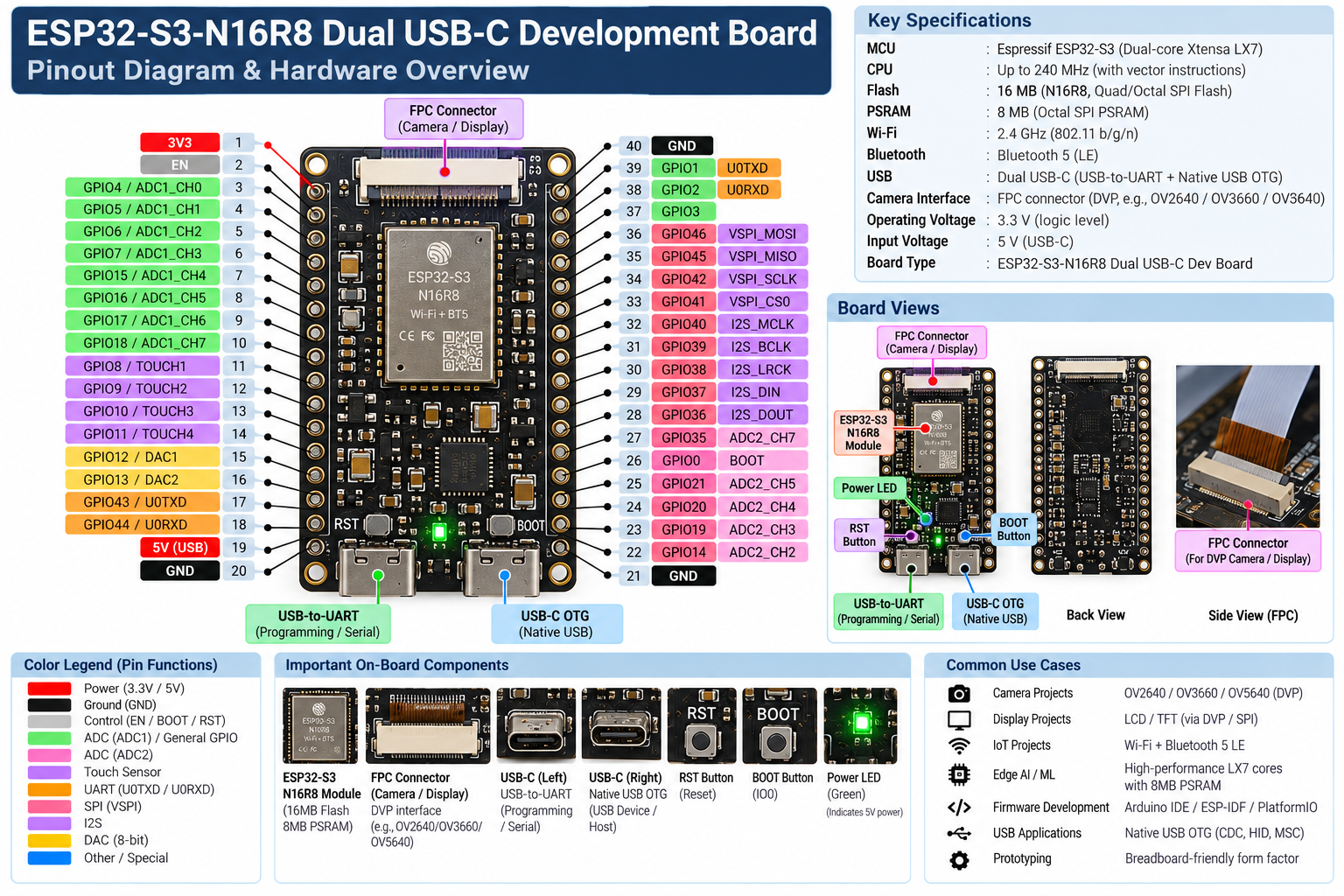
This document is prepared for the ESP32-S3-N16R8 development board used in the project. It combines the board information provided in the project documentation with the current Arduino IDE configuration.
1. Board Overview
The project uses an ESP32-S3-N16R8 dual USB-C development board, mounted on a standard solderless breadboard.
The board is based on Espressif's ESP32-S3 SoC and is intended for embedded, IoT, USB, camera/display, and edge-AI/ML applications.
Board Identity
Property Project Configuration
Board ESP32-S3-N16R8 Dual USB-C Development Board
MCU Espressif ESP32-S3
CPU Dual-core 32-bit Xtensa LX7
Maximum CPU Frequency Up to 240 MHz
Flash 16 MB
PSRAM 8 MB OPI PSRAM
Wi-Fi 2.4 GHz, IEEE 802.11 b/g/n
Bluetooth Bluetooth 5 LE
USB Dual USB-C
Camera/Display Interface FPC connector for DVP camera/display modules
Boot Control BOOT / IO0 button
Reset Control RST button
Power Indicator On-board power LED
Physical Setup Mounted across the center divider of a solderless breadboard
2. ESP32-S3 MCU
2.1 Processor
The ESP32-S3 contains a:
- Dual-core 32-bit Xtensa LX7 processor
- Operating frequency up to 240 MHz
- Vector instructions useful for computationally intensive workloads, including AI/ML-oriented processing
Why the ESP32-S3 is useful for this project
The combination of:
- dual CPU cores,
- high clock frequency,
- 8 MB PSRAM,
- Wi-Fi,
- Bluetooth LE,
- USB,
- camera/display interfacing,
makes the ESP32-S3 suitable for embedded vision, IoT, edge processing, and firmware development.
3. Memory Configuration
The board uses the N16R8 memory configuration.
3.1 Flash Memory
16 MB Flash
Flash is non-volatile memory and is used for persistent program/storage requirements such as:
- Firmware
- Bootloader
- Partition information
- Application data, depending on the project
Project Arduino configuration
Flash Size: 16MB (128Mb)
Flash Mode: QIO
Flash Frequency: 80 MHz
3.2 PSRAM
8 MB OPI PSRAM
PSRAM is external RAM used when the application needs more working memory than the internal SRAM can provide.
It is especially useful for:
- Camera frame buffers
- Large image buffers
- Display buffers
- Large temporary data structures
- Memory-intensive processing
- Edge AI/ML workloads
Project configuration
PSRAM: OPI PSRAM
Capacity: 8 MB
Key distinction: Flash is primarily persistent storage; PSRAM is working memory used while the application is running.
4. Wireless Connectivity
4.1 Wi-Fi
The ESP32-S3 provides:
- 2.4 GHz Wi-Fi
- IEEE 802.11 b/g/n
Typical embedded uses include:
- Connecting the device to a local network
- Sending sensor/image data
- Communicating with web servers
- IoT applications
- Cloud/API communication
- Remote monitoring
4.2 Bluetooth
The board supports:
- Bluetooth 5
- Bluetooth Low Energy (BLE)
BLE is useful for low-power communication between the board and nearby devices.
5. Dual USB-C Architecture
One of the important characteristics of this development board is its two USB-C ports.
USB Port 1 --- USB-to-UART
The USB-to-UART interface is intended for:
- Programming
- Serial communication
- Serial monitor/debugging
- Firmware upload
This is the conventional development/programming connection.
USB Port 2 --- Native USB OTG
The second USB-C interface is connected to the ESP32-S3's native USB functionality.
Potential uses include:
- USB device applications
- USB host/OTG applications
- USB CDC
- HID
- Other native USB functionality supported by the firmware
Mental model
Computer
   │
   ├── USB-to-UART USB-C
   │       └── Programming / Serial
   │
   └── Native USB USB-C
           └── ESP32-S3 Native USB / OTG
6. FPC Camera / Display Connector
The board contains a central FPC (Flexible Printed Circuit) connector.
The connector is intended for interfaces such as:
- DVP camera modules
- Display interfaces
The board description indicates compatibility with DVP camera modules such as:
- OV2640
- OV5640
- Other compatible camera modules
The project's earlier documentation also identifies an OV3660 3-megapixel camera sensor as the project camera. Treat the actual project camera model as project-specific and verify it against the final hardware configuration.
6.1 Why the FPC Connector Matters
Camera applications generate large amounts of data.
A camera frame can require significant RAM depending on:
- Resolution
- Pixel format
- Number of frame buffers
- Image-processing requirements
This is one reason the project's 8 MB OPI PSRAM is important.
Simplified camera data path
Camera Sensor
     │
     │ DVP / FPC
     ▼
ESP32-S3
     │
     ├── PSRAM → Frame Buffer
     │
     ├── CPU → Processing
     │
     └── Wi-Fi / USB → Data Transfer
7. On-Board Controls
7.1 RST Button
The RST (Reset) button resets the ESP32-S3.
Typical use:
- Restart firmware
- Recover from a running application
- Reset the board during development
7.2 BOOT Button
The BOOT / IO0 button is used for boot/programming-related operations.
It is commonly involved when placing the ESP32-S3 into its bootloader/download mode.
Typical programming concept
BOOT / IO0
     +
Reset
     ↓
Bootloader / Download Mode
     ↓
Firmware Upload
The exact button sequence can depend on the board's USB/programming implementation.
8. Power Indicator
The board includes an on-board power LED.
In the current board state:
- The board is powered through the primary USB-C connection.
- The green power indicator is illuminated.
The LED provides a quick visual indication that the board is receiving power.
9. GPIO Overview
The ESP32-S3 provides a large set of configurable GPIOs.
Depending on the specific board design and how peripherals are routed, GPIOs can be used for functions including:
- Digital input
- Digital output
- ADC
- UART
- SPI
- I2S
- Touch sensing
- Camera interfaces
- Other peripheral functions
Important: GPIO availability and alternate-function assignments depend on the exact board design and ESP32-S3 variant. Do not treat a generic ESP32-S3 DevKit pinout as the definitive pinout for this board.
9.1 GPIO Mental Model
A GPIO is not necessarily limited to one function.
Conceptually:
                    GPIO
                     │
       ┌─────────────┼─────────────┐
       │             │             │
   Digital I/O      ADC          Peripheral
                                   │
                         ┌─────────┼─────────┐
                         │         │         │
                       UART       SPI       I2S
The firmware configures the required peripheral function for the selected GPIO.
10. Important ESP32-S3 Pin Functions
The following are the major peripheral categories relevant to studying this board.
Function Purpose
GPIO General digital input/output ADC Analog signal measurement UART Serial communication SPI High-speed synchronous communication I2S Digital audio / streaming data USB Native USB functionality Camera/DVP Camera data interface Touch Capacitive touch sensing DAC Analog output functionality where supported PWM Hardware-controlled pulse-width modulation
11. Pinout Reference
Power / Control Pins
Pin Type Function
3V3 3.3 V supply/output rail 5V / VBUS USB-derived 5 V rail where exposed GND Ground EN / Reset Chip enable/reset control BOOT / IO0 Boot/download control
GPIO / Peripheral Reference
A typical ESP32-S3 GPIO reference includes functions such as:
GPIO Group Possible Functions
GPIO0 Boot-related function / GPIO
GPIO1--GPIO3 GPIO / UART-related functions depending on configuration
GPIO4--GPIO7 GPIO / ADC1 channels
GPIO8--GPIO11 GPIO / touch-related functions
GPIO12--GPIO13 GPIO / DAC-related functions where supported
GPIO14--GPIO21 GPIO / ADC2 or peripheral functions
GPIO35--GPIO40 GPIO / I2S and other peripheral functions
GPIO41--GPIO46 GPIO / SPI and UART-related functions depending on configuration
Pin mapping warning: The table above is a functional study reference, not a replacement for the exact schematic of the specific dual-USB-C board. Camera routing, USB routing, boot straps, and board-specific connections can reserve or constrain individual pins.
12. Arduino IDE Configuration
The current project uses the Arduino IDE.
Tools Configuration
Board:
ESP32S3 Dev Module

Flash Size:
16MB (128Mb)

PSRAM:
OPI PSRAM

Flash Mode:
QIO

Flash Frequency:
80MHz

USB CDC On Boot:
Enabled
These settings are important because they tell the Arduino toolchain how the firmware should be built and how the board's memory/USB configuration should be handled.
13. USB CDC On Boot
The project has:
USB CDC On Boot: Enabled
CDC stands for Communication Device Class.
When supported/configured through the ESP32-S3's native USB interface, USB CDC can provide a virtual serial communication channel over USB.
Concept
ESP32-S3 Native USB
        │
        ▼
USB CDC
        │
        ▼
Computer recognizes serial interface
This can be useful for:
- Serial logging
- Debug output
- Development communication
14. Flash Mode --- QIO 80 MHz
The current project configuration uses:
Flash Mode: QIO
Flash Frequency: 80 MHz
QIO
QIO refers to Quad I/O flash access.
It allows multiple data lines to be used for flash communication, providing higher throughput than single-line access.
Why it matters
The flash configuration affects how the ESP32-S3 communicates with external flash memory during program execution and data access.
15. Breadboard Integration
The development board is currently mounted across the center divider of a standard solderless breadboard.
This arrangement is useful because:
- Both sides of the board expose GPIO pins.
- External sensors/modules can be connected easily.
- Jumper wires can be routed from either side.
- The board remains mechanically stable during prototyping.
Physical arrangement
GPIO Pins       ESP32-S3-N16R8       GPIO Pins
──────────      ┌─────────────┐      ──────────
                │             │
                │   ESP32-S3  │
                │             │
──────────      └─────────────┘      ──────────
       ═════════ Breadboard ═════════
16. Current Board State
The current physical setup is:
- ESP32-S3-N16R8 mounted on a solderless breadboard.
- Board powered through the primary USB-C connection.
- Green power LED illuminated.
- GPIO pins exposed for external prototyping.
- FPC connector available for camera/display connection.
- RST and BOOT buttons accessible on the board.
17. Hardware Architecture
                    ESP32-S3-N16R8
                           │
        ┌──────────────────┼──────────────────┐
        │                  │                  │
        ▼                  ▼                  ▼
   16 MB Flash         8 MB PSRAM       Wireless
        │                  │             │
        │                  │        ┌────┴────┐
        │                  │        │         │
        │                  │       Wi-Fi    BLE
        │                  │
        └──────────┬───────┘
                   │
                   ▼
              ESP32-S3 CPU
                   │
       ┌───────────┼───────────┐
       │           │           │
       ▼           ▼           ▼
      GPIO      FPC/DVP      USB
       │           │           │
       ▼           ▼      ┌────┴────┐
   Sensors/IO    Camera   UART     Native
                            │        │
                            ▼        ▼
                         PC/Serial   USB/OTG
18. Project Camera Architecture
When the project camera is connected through the FPC/DVP interface:
Camera
  │
  │ DVP data/control
  ▼
FPC Connector
  │
  ▼
ESP32-S3
  │
  ├── Capture frame
  │
  ├── Store/buffer in PSRAM
  │
  ├── Process frame
  │
  └── Transfer/store result
The exact camera pin mapping and initialization parameters should come from the project's firmware configuration.
19. Why 8 MB PSRAM Matters for Camera Projects
A camera application can require substantially more memory than a simple sensor application.
For example:
Camera frame
     ↓
Frame buffer
     ↓
PSRAM
     ↓
Image processing
     ↓
Output / transmission
PSRAM provides additional working memory for these buffers.
This is particularly important when dealing with:
- Higher-resolution frames
- Multiple frame buffers
- JPEG/image processing
- Computer-vision pipelines
- AI/ML inference buffers
20. USB Architecture --- Practical Comparison
Feature USB-to-UART Native USB
Programming Yes Can be used depending on configuration
Serial monitor Yes Yes with USB CDC
Native USB features No Yes
USB OTG No Yes
Typical development use Programming/debugging USB applications / native USB
21. Firmware Development Flow
Write Firmware
      ↓
Compile
      ↓
Link / Generate Firmware Image
      ↓
Connect ESP32-S3
      ↓
Enter Programming Mode if required
      ↓
Flash Firmware
      ↓
Reset / Boot
      ↓
Firmware Starts
      ↓
Serial / USB Debugging
      ↓
Test Hardware
22. Typical Firmware Startup Flow
A project firmware can conceptually follow:
Power On
   ↓
Boot ROM / Bootloader
   ↓
Application Startup
   ↓
Initialize Serial / USB
   ↓
Initialize GPIO
   ↓
Initialize Camera / Sensors
   ↓
Initialize Wi-Fi / Communication
   ↓
Allocate Buffers
   ↓
Start Main Application
   ↓
Continuous Processing
The exact order depends on the project's actual firmware implementation.
23. Development Environment
Current Project Tooling
IDE:
Arduino IDE

Board Selection:
ESP32S3 Dev Module

Flash:
16 MB

PSRAM:
OPI PSRAM

Flash:
QIO @ 80 MHz

USB CDC:
Enabled
The project can also use the ESP32 development ecosystem and compatible libraries for camera, Wi-Fi, USB, and peripheral control.
24. Common Applications of This Board
The hardware configuration is suitable for:
Camera / Vision
- Camera capture
- Image processing
- Computer vision
- Embedded vision
- Edge-AI prototypes
IoT
- Wi-Fi sensors
- Cloud-connected devices
- Remote monitoring
- Data collection
USB
- USB CDC
- USB HID
- USB device applications
- USB OTG/host applications
Embedded Systems
- Sensor interfacing
- GPIO control
- Motor/control prototypes
- Communication peripherals
Displays
- Camera/display interface projects
- SPI displays
- Other compatible display interfaces
25. Important Hardware Concepts to Remember
ESP32-S3
MCU
→ Dual-core Xtensa LX7
→ Up to 240 MHz
→ Wi-Fi + Bluetooth LE
→ USB
→ Large peripheral set
N16R8
N16
→ 16 MB Flash

R8
→ 8 MB OPI PSRAM
Dual USB-C
USB-C #1 → USB-to-UART / programming / serial
USB-C #2 → Native USB / OTG
FPC
FPC
→ Flexible Printed Circuit connector
→ Camera / display interface
26. Common Mistakes
Do not assume every ESP32-S3 board has the same physical pinout.
Different ESP32-S3 development boards can:
- Route GPIOs differently
- Reserve GPIOs for cameras
- Reserve GPIOs for USB
- Expose different power pins
- Use different USB interfaces
- Use different flash/PSRAM configurations
Always distinguish:
ESP32-S3 chip pin/function
        ≠
Specific development board pinout
For this project, the exact board schematic/pinout should be the final authority for wiring.
27. Quick Specification Sheet
Category Specification
MCU ESP32-S3 CPU Dual-core Xtensa 32-bit LX7 Frequency Up to 240 MHz Flash 16 MB PSRAM 8 MB OPI Wi-Fi 2.4 GHz 802.11 b/g/n Bluetooth Bluetooth 5 LE USB Dual USB-C USB Interface 1 USB-to-UART USB Interface 2 Native USB OTG Camera/Display FPC / DVP interface Boot BOOT / IO0 Reset RST Indicator Power LED Development Board ESP32-S3-N16R8 Project IDE Arduino IDE Board Setting ESP32S3 Dev Module Flash Setting 16MB (128Mb) PSRAM Setting OPI PSRAM Flash Mode QIO Flash Frequency 80 MHz USB CDC On Boot Enabled Physical Setup Solderless breadboard
28. Interview / Viva Questions
Q1. What microcontroller does the board use?
ESP32-S3, featuring a dual-core 32-bit Xtensa LX7 processor running up to 240 MHz.
Q2. What does N16R8 mean?
N16R8 refers to the board's memory configuration:
- N16 → 16 MB Flash
- R8 → 8 MB PSRAM
Q3. Why is PSRAM important in a camera project?
Camera applications need large buffers for image frames. The 8 MB OPI PSRAM provides additional working memory for frame buffers and image processing.
Q4. Why are there two USB-C ports?
One provides USB-to-UART functionality for programming and serial communication, while the other provides native USB/OTG functionality.
Q5. What is the FPC connector used for?
It provides an interface for compatible DVP camera or display modules.
Q6. What is the difference between Flash and PSRAM?
Flash is non-volatile storage, while PSRAM is volatile working memory used during program execution.
Q7. What is USB CDC?
USB CDC allows the ESP32-S3's native USB interface to provide a USB communication/serial interface to the host computer.
Q8. Why configure PSRAM as OPI?
The board uses 8 MB OPI PSRAM, and selecting the corresponding configuration allows the firmware environment to correctly initialize and use that external memory.
Q9. Why is QIO 80 MHz configured?
It specifies the flash access mode and clock frequency used by the firmware environment for external flash communication.
Q10. Why can't you blindly use another ESP32-S3 board's pinout?
Because development boards can route, reserve, or expose GPIOs differently even when they use the same ESP32-S3 family MCU.
29. Final Mental Model
                         ESP32-S3-N16R8
                                │
              ┌─────────────────┼─────────────────┐
              │                 │                 │
          Processing          Memory           Connectivity
              │                 │                 │
        Dual-core LX7      16 MB Flash       Wi-Fi 2.4 GHz
          240 MHz          8 MB PSRAM        Bluetooth 5 LE
              │
              ├──────────────┐
              │              │
           GPIOs          Peripherals
              │              │
       ┌──────┼──────┐   ┌───┼────┬────┐
       │      │      │   │   │    │    │
      ADC   UART    PWM SPI I2S  USB  Camera
                                     │
                                     ▼
                                  FPC/DVP
                                     │
                                     ▼
                                   Camera

USB-C #1 → USB-to-UART → Programming / Serial
USB-C #2 → Native USB  → USB / OTG

Flash → Firmware / Persistent Storage
PSRAM → Runtime Buffers / Camera Frames / Processing
30. One-Page Revision
ESP32-S3-N16R8 = Dual-core LX7 + 16 MB Flash + 8 MB OPI PSRAM + Wi-Fi + BLE + Dual USB-C + FPC camera/display interface.
Remember these first:
MCU       → ESP32-S3
CPU       → Dual-core Xtensa LX7
Speed     → Up to 240 MHz
Flash     → 16 MB
PSRAM     → 8 MB OPI
Wi-Fi     → 2.4 GHz 802.11 b/g/n
Bluetooth → 5 LE
USB #1    → USB-to-UART
USB #2    → Native USB OTG
Camera    → FPC / DVP
Boot      → IO0 / BOOT
Reset     → RST
IDE       → Arduino IDE
Board     → ESP32S3 Dev Module
Project-specific rule: For actual wiring and GPIO assignments, always use the schematic/pinout of the exact ESP32-S3-N16R8 board used in the project. Generic ESP32-S3 DevKit pinouts should only be treated as reference material.
🧭 Continue Learning
Related technical blueprints and practical guides in Firmware & Embedded Systems.

Embedded C Interview Preparation
Frequently tested concepts, Practical Embedded C programs
Microcontroller-Specific Embedded C
Embedded C is not completely platform-independent. You should learn the concepts above and then implement them on a real microcontroller
Debugging, Testing and Production Firmware
Hardware debugging, Firmware testing, Reliability, Security, Performance,...
Advanced Firmware Development
ADC, DAC and Sensor Interfacing, DMA and Data Transfer, Embedded Software Architecture, RTOS — Real-Time Operating Systems, Embedded Build Process and Linker